

What Speeds and Feeds Should You Use for Carbide Taps in Aluminum
2026-07-02
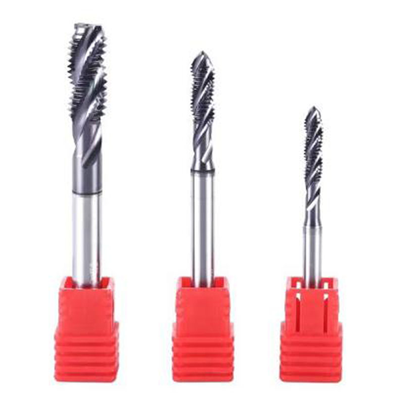
Aluminum is one of the most machinable metals, but tapping it successfully with a Carbide Tap requires a precise balance of speed, feed, and coolant strategy. Many shops treat aluminum as “easy,” yet broken taps and poor thread quality remain common—especially when using solid Carbide Tap tooling. At NERES, we have engineered our Carbide Tap series specifically for high-volume aluminum production, and the single most frequent question we receive is: What are the actual speeds and feeds that work?
The short answer: for most wrought aluminum alloys (6061, 7075, 2024), a Carbide Tap performs optimally between 30–60 SFM (surface feet per minute) for manual cycles, and up to 80–150 SFM on rigid CNC tapping heads with through-spindle coolant. But that range is meaningless without understanding thread depth, coating, and chip evacuation. This guide breaks down the math, the adjustments, and the real-world rules that keep your NERES Carbide Tap cutting cleanly, predictably, and profitably.
The Baseline Speed and Feed Formula for Carbide Taps in Aluminum
All tapping feeds are derived from the spindle RPM, which comes from SFM. For a Carbide Tap, the feed rate equals the thread pitch (in inches or mm per revolution) multiplied by RPM—because tapping is a rigid synchronous operation.
Step 1 – Calculate RPM:
RPM = (SFM × 3.82) / Tap Diameter (inches)
Step 2 – Set Feed:
Feed (IPM) = RPM × Thread Pitch (inches per thread)
For metric: Feed (mm/min) = RPM × Pitch (mm)
Recommended Starting Speeds by Aluminum Alloy Group
The table below reflects validated data from NERES in-house testing using uncoated and TiAlN-coated Carbide Tap geometries. These values assume a blind hole at 1.5× diameter depth, with 8–10% thread engagement.
| Aluminum Alloy | Hardness (HB) | Starting SFM (CNC Rigid) | Max SFM (with Through-Coolant) | Feed Adjustment |
|---|---|---|---|---|
| 6061-T6 / 7075-T6 | 95–105 | 50 – 70 | 120 | Standard |
| 2024-T4 / 2014-T6 | 120–135 | 40 – 55 | 90 | Reduce 15% |
| 5052-H32 / 3003-H14 | 60–75 | 60 – 85 | 150 | Increase 10% |
| Cast Aluminum (A380) | 80–90 | 35 – 50 | 75 | Reduce 20% (abrasive) |
| 7050-T7451 (aerospace) | 135–150 | 30 – 45 | 70 | Use coated NERES Carbide Tap |
Critical rule: Never use the maximum SFM for the first 50 holes. Start at 60% of the table value, check thread finish and taper wear, then ramp up in 5 SFM increments. A NERES Carbide Tap maintains flank wear below 0.002” even at 100 SFM when coolant concentration is kept above 8%.
Three Non-Negotiable Feed Adjustments for Aluminum
Aluminum’s ductility creates a built-up edge (BUE) risk. Feed must be high enough to take a continuous chip, but not so high that the Carbide Tap’s flutes pack solid.
-
For spiral point taps (through-holes): Increase feed by 5% over calculated value to shear the chip forward.
-
For spiral flute taps (blind holes): Use calculated feed exactly—never reduce feed, as this rubs rather than cuts, work-hardening the aluminum.
-
For forming (roll) taps: Feed equals pitch × RPM, but SFM drops to 20–40 because forming generates more heat. NERES recommends a forming Carbide Tap only for alloys below 100 HB.
Coolant and Chip Evacuation – The Overlooked Speed Multiplier
Without proper lubrication, even the best Carbide Tap fails in aluminum. The feed rate assumes a chip that flows freely. Use these NERES-approved guidelines:
-
Flood coolant: Minimum 8% semi-synthetic emulsion, directed at the tap entry, not the spindle.
-
Through-spindle coolant (TSC): Allows a 25–30% SFM increase—this is where NERES Carbide Tap with internal coolant holes outperforms competitors.
-
MQL (minimum quantity lubrication): Reduce SFM by 20% and increase feed by 3% to compensate for reduced heat transfer.
Common Mistakes That Destroy Carbide Taps in Aluminum
-
Using the same feed for peck tapping – each retract and re-enter multiplies thermal shock. Reduce SFM by 15% for peck cycles.
-
Ignoring hole preparation – a drilled hole that is 0.002” undersized increases torque by 40%, forcing feed deviation. Always use a NERES-suggested drill diameter for 65% thread.
-
Rigid vs. floating holders – a floating holder on a rigid CNC changes effective feed by 0.001–0.002” per revolution, causing taper. Always use a rigid holder with a Carbide Tap in aluminum.
Carbide Tap FAQ – Expert Answers from NERES Engineers
Q: Can I run the same speeds and feeds for a Carbide Tap in aluminum as I do for cobalt HSS taps?
A: Absolutely not. A Carbide Tap has approximately 3× the modulus of elasticity of HSS, meaning it transfers heat into the tool rather than the chip. Running a Carbide Tap at HSS speeds (typically 20–30 SFM) causes rubbing, not cutting—this generates friction, work-hardens the hole, and leads to sudden brittle fracture. For aluminum, a NERES Carbide Tap should always be run at least 40% faster than a cobalt tap, but with rigid feed synchronization. If you switch from HSS to Carbide Tap, increase SFM by 30–50% and keep the feed-per-revolution exactly equal to the pitch—never deviate.
Q: How do I adjust speeds and feeds when tapping deep blind holes (over 2× diameter) in aluminum with a Carbide Tap?
A: Depth changes chip evacuation more than cutting forces. For blind holes deeper than 2× diameter, reduce your starting SFM by 25% and use a spiral flute Carbide Tap specifically designed for chip pulling. Feed remains at pitch × RPM, but you must program a peck cycle with a retract of 0.040” every 0.200” of depth. At NERES, we recommend lowering the feed override to 95% during the first 0.100” of engagement to let the taper lead align, then returning to 100% feed. Also, increase coolant concentration to 10–12% for deep holes—this lowers the coefficient of friction and allows a 10 SFM increase after every 100 parts, as the tap thermally stabilizes.
Q: Why does my Carbide Tap show flank wear after only 200 holes in 6061, even though I use the recommended speed?
A: Flank wear in aluminum is almost never a speed issue—it is a chip recutting problem. When aluminum chips pack into the flutes of a Carbide Tap, they act as abrasives, wearing the carbide substrate faster than the cutting edge. Check your feed: if you reduced feed to “play safe,” you are thinning the chip, causing it to curl back into the flank. Increase feed back to 100% of pitch × RPM. Second, verify your hole diameter: for 6061 with a NERES Carbide Tap, use a drill that produces 65% thread height (e.g., for a 1/4-20 tap, use a #7 drill instead of #8). Third, inspect your coolant nozzle—it must hit the tap flute entry, not the top of the hole. If wear persists, switch to a NERES TiCN-coated Carbide Tap, which reduces adhesion and extends tool life to 800+ holes in 6061.
Final Process Checklist for Production Tapping
| Parameter | Recommended Setting for NERES Carbide Tap in Aluminum |
|---|---|
| Spindle synchronization | Rigid tapping (G84.2) – no floating holder |
| Coolant pressure | 300–500 PSI (minimum 150 PSI for TSC) |
| Coolant concentration | 8–10% water-soluble oil (chlorine-free) |
| Thread engagement | 60–65% (reduce to 55% for 7075) |
| Peck retract distance | 0.020” – 0.040” (blind holes only) |
| Tool runout (TIR) | Below 0.0005” at the gage line |
Putting It All Together – Your Production Strategy
Start every new aluminum job with a conservative 40 SFM on your NERES Carbide Tap, run 10 test holes, measure the go/no-go gauge fit, and examine the chip shape. A good chip from a Carbide Tap in aluminum is a tight spiral, silver in color, and falls freely. If the chip is smoky or blue, reduce SFM by 10. If the chip is powdery, increase SFM by 5 and check your feed synchronization. Document every adjustment—because aluminum alloys vary by heat treatment and billet source, your final speed may differ by ±15 SFM from the tables. That is normal.
For high-mix, low-volume shops, keep a dedicated NERES Carbide Tap per alloy family and never share taps between 6061 and cast aluminum—the abrasive silicon in cast alloys changes the wear pattern and will distort your feed calculations.
Contact NERES for Custom Speeds and Feeds Support
Every tapping application has unique variables—machine rigidity, holder style, workpiece fixturing, and even ambient shop temperature affect how a Carbide Tap performs in aluminum. The tables and formulas above give you a science-based starting point, but we know that production floors need site-specific answers.
Contact NERES today with your part drawing, alloy grade, hole depth, and machine model. Our application engineers will generate a tailored speed/feed recipe for your Carbide Tap, including a tool life prediction and a coolant optimization plan. We also offer free test taps for qualified high-volume programs. Reach out through our website or call your local NERES distributor—we respond within one business day with data, not guesses. Let us help you double your tapping productivity before your next shift.